Time to Prepare for Winter
by Dan Dvorak, DuPont Engineering Technology
Featured in Chemical Processing Magazine – July, 2004

Winter can cast a chill over plant operations. Delivering a process fluid at specific conditions can become difficult when significant temperature changes negatively impact fluid physical properties such as freeze point, viscosity and moisture content. Likewise, the performance of utility streams such as water, compressed gases and organic heat-transfer media can suffer at ambient temperatures below their freezing or dew points. To avoid such problems, plants must take adequate steps to maintain specific temperatures of fluid systems.
Maintaining these temperatures demands an understanding of process heat loss and methods used to limit or make up for such a loss. Insulation plays a key role, but so does heat tracing. In this article, we will specifically focus on the right way to provide steam tracing.
Insulation isn’t enough Insulation is important; it’s a relatively inexpensive way to reduce heat loss. Always keep in mind, though, that insulation reduces — but does not eliminate — heat loss. In process fluid applications, this heat loss will result in lower fluid temperatures over time. Even with insulation, outside utility service systems subject to cold ambient conditions can suffer freeze-ups during periods of intermittent or reduced fluid flow.
Heat loss for a specified process pipe size, insulation type and thickness varies with the temperature differential between the process fluid and ambient conditions. For a 3-in., Schedule 40 pipe with 1.5-in. calcium silicate insulation carrying fluid at 175°F and subject to an ambient temperature of 0°F, heat loss might amount to 63 Btu/hr-ft. That doesn’t seem like all that much. In reality, however, a large manufacturing operation that relies on a process fluid whose temperature control is somewhat critical would have to make up considerable amounts of heat loss to simply keep this system in operation. In addition, this incremental heat, in today’s volatile energy market, comes at considerable cost.
This is where heat tracing comes in. Typical heat-tracing systems use steam, heat-transfer fluids or electricity to overcome incremental heat loss. Such systems perform two vital functions: They replace incremental heat loss through insulation and provide freeze protection by maintaining a temperature above the freeze point.
Heat tracing can clearly impact both operability and cost. Depending upon the application, the stake associated with poor heat-tracing system design, improper installation or inadequate operating and maintenance practices can be significant.
Ultimately, results of poor heat-tracing system performance can include:
• Unscheduled area or complete site outages.
• Increased system maintenance costs.
• Poor process control.
• Process safety or environmental-related incidents.
Given the potential business impact, it’s important to understand and respect the role heat tracing systems and components play in maintaining safe, reliable and cost-efficient operations.
Steam’s attraction, the availability of steam at most plant sites, coupled with its thermodynamic properties and relative ease of use, make it an attractive heat-transfer media for many heat-tracing applications. Steam-tracing system designs use pipe jacketing, relatively small-diameter pipe or tubing that is attached to process piping or vessels. Theoretically, steam flowing through the tracer pipe or tube will give up its latent heat to the heated pipe and condense at constant temperature. Although process temperatures may require application of high-pressure steam, pressures found in steam tracer systems commonly are less than 250 psig. Heat transfer can occur via either conduction or convection.
Jacketed piping, direct-contact bare tubing and tubing that is bonded to the surface by solid heat-transfer material are examples of conduction-type steam tracing. Applications requiring critical temperature control, high temperatures or uniform pipe-wall temperatures often rely on fixed jacketed piping or “bolt-on” versions.
Tubing-type steam tracers bonded to the surface with a solid heat-transfer material have proved to be extremely cost-effective alternatives to the jacketed design. The bonding material acts to increase both the heat transfer coefficient and heat transfer area. It allows greater heat input compared to a plain tracer in contact with the surface. Generally speaking, these types of tracers are used when temperature requirements exceed 175°F. Typically, tubing materials are copper for temperatures up to 400°F, and stainless steel for higher temperatures; tubing sizes usually are in the 3/8-in. to 3/4-in. range, although larger tubing and even pipes sometimes are used.
Convective-type steam tracers generally employ tape instead of heat-transfer material to attach the tubing to the surface. Air convection movement between the tracer and the surface transfers the heat. Bare tubing can be used, typically with spacers to keep it off the surface. An alternative design uses tubing with some form of covering or jacket that reduces thermal conductivity. This “light” or “isolated” design can closely match input requirements and avoid localized hot spots and issues of spacer location, attachment and movement during installation. These types of tracers usually suit applications with lower temperature requirements, say, under 175°F.
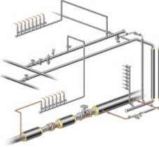
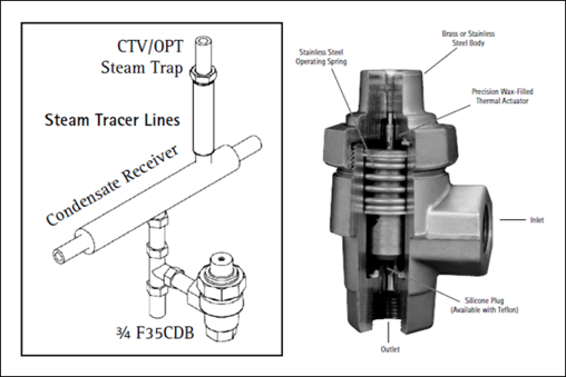
Figure 1 shows a typical steam-tracing installation for maintaining a specified process-fluid temperature range. The installation consists of steam-supply piping, manual isolation valves, control valves, tracer tubing, the heated fluid piping system, insulation; steam trap and condensate return piping.
Figure 1. This arrangement is often used for maintaining a process fluid at a specified temperature. Source: Tracer Div., Tyco Thermal Controls
Succeeding at design
Developing a steam-tracing system similar to that depicted in Figure 1 requires an understanding of several key items:
• Process system parameters:
• Pipe size(s), diameter and length.
• Materials of construction (particularly their susceptibility to hot spots, stress corrosion cracking and other impacts from steam tracing).
• Equipment and components.
• Physical location, whether outdoors, indoors or underground.
• Type and thickness of insulation.
• Process fluid parameters:
• Low- and high-temperature limits (i.e., expected alarm points).
• Standard operating temperature or temperature range (i.e., expected operational set point or normal system operating temperature range).
• Steam system conditions:
• Pressure and temperature steam available.
• Condensate-return system pressure.
• Proximity of steam and condensate return tie-in points.
• Ambient conditions:
• Lowest ambient temperature.
• Wind speed at lowest ambient temperature.
Take advantage of the extensive literature on design, installation and operation that steam-tracing system and component manufacturers provide. Some vendors and specialists give step-by-step procedures that you can use, once armed with the basic information listed above, to select tracer types and lengths. In addition, these manufacturers offer technical services or software to aid in detailed design and system analysis.
A balancing act
During the design evaluation phase, users often must balance a number of factors to come up with the lowest investment and operating costs. These issues include:
• Initial investment:
• Type of tracers.
• Size, length and number of tracers.
• Scope of auxiliary components, such as isolation valves, drain valves, supply-and-return connections, steam traps, etc.
• Operating costs:
• Energy efficiency.
• System or component maintenance.
Here are five tips to help you in the design evaluation process:
1. Select between conduction and convection tracing largely on the basis of the process temperature requirement and the nature of the application. Generally speaking, conduction- type tracers are used when process temperature ranges exceed 175°F. Bare convection-type tracers are typically employed below 175°F. Convection-type tracers with coverings or jackets usually suit lower temperature ranges, say, below 100°F, or freeze protection applications.
2. Limit, when possible, the number of tracers to one per application or piping run. However, an application deemed critical may merit more than one tracer. An additional tracer will require separate supply and return manifold connections, valves, steam trap and fittings, thus increasing installation costs.
3. Theoretical tracer lengths are based on steam supply pressure, heat-transfer surface area or length, tubing size, type of insulation and temperature requirements. For actual installations, consider the steam header size, number of tracer system fittings or bends, increases in elevation, steam-trap pressure drop and condensate-return header pressure.
4. Take into account cold startup loads when assessing tracer lengths. Condensate loads associated with startup conditions can impact heat-up rates; pressure drop and steam trap capacity.
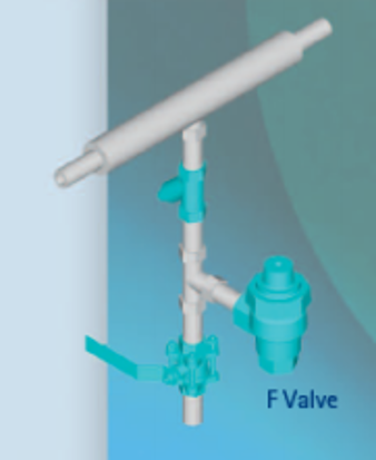
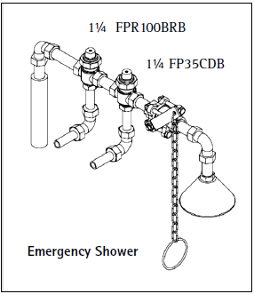
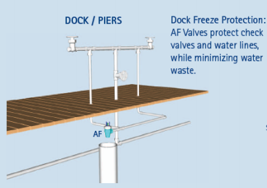
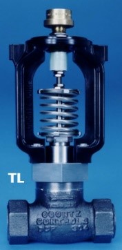
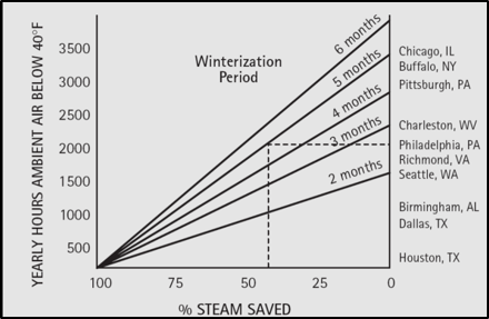
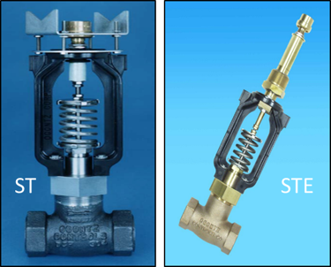
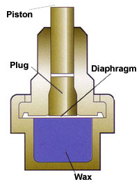
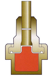
5. Equip steam tracers used for freeze protection with temperature-actuated valves. Application of these valves in an
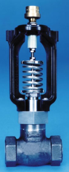
on/off operating strategy helps reduce costs by using the steam tracer only when required. For example, a small group of tracers could be controlled by a valve that would open when ambient temperature falls to 5°F above the process freezing point and close when ambient temperature rises to 10°F above the freezing point. Figure 2 depicts such a valve.
Installation tips
At times, some of the most basic design concepts, good engineering and proper installation practices are overlooked during system installation. To avoid such mishaps, pay attention to the following points:
1. Steam supplied to tracers should come off the top of steam headers to ensure that the steam supply is dry. Never use a low point drain or steam header drip pocket as a source for steam.
2. The steam supply tie-in point should be located so that steam is available during periods when the manufacturing process is shut down.
3. Each tracer loop should have its own steam supply, steam trap and condensate return. This will eliminate any steam circuit bypassing or recirculating.
4. Tracing steam supply should allow gravity draining. In vertical applications, the steam and condensate flow must be from top to bottom. In horizontal applications, steam and condensate flow should follow the direction of downward slope.
5. Steam tracers should not be spiral-wound around horizontal piping.
6. Tracer installation on process piping should take into account the potential for damage from piping supports when installed. This may prompt a change in tracer orientation (bottom to top) and insulation installation.
7. Tracing should be free of kinks and bends that result in tube “flattening,” i.e., more than a 33% reduction in outside diameter.
8. Condensate lines from tracer steam traps should be installed horizontally or with a downward slope whenever possible.
9. Critical process instruments mounted outdoors should be installed in weatherproof enclosures.
10. No tracer tubing joints should be located beneath the heated piping or vessel insulation. These joints should be located at points such as process piping flanges, tracing loops or expansion loops, where necessary, and in the vicinity of equipment or components that may require maintenance or removal.
11. Tracer steam-supply valves and traps should be marked and clearly identified for operations and maintenance personnel.

Figure 2. Self-contained on/off valves such as this one enable users to employ tracing only when necessary. Source: Ogontz Corporation
An effective program As stated earlier, poor tracing-system installation or operation can lead to serious consequences.
The “out-of-sight/out-of-mind” nature of the installations led to a false sense of security. Unfortunately, this is all too common. As a result, steam-tracing systems receive little priority as well as little, if any, attention from operations or maintenance.
Two important improvement items common to all of these events bear discussion: basic awareness of steam tracing systems, and operations and maintenance practices for the systems.
One way of addressing both issues is to include steam tracing in a site-wide steam-system management program. Such a program should incorporate efforts to reduce energy consumption while ensuring all portions of a steam system are maintained and available for operation. In essence, it provides a process by which operations and maintenance efforts can help decrease inefficiencies while maintaining system integrity and reliability. A steam-system management program can include such initiatives as automation of operations, energy efficiency and energy conservation.
Here’s how one site handles steam tracing systems as part of a steam-system management program: The site-wide program includes basic energy conservation initiatives such as steam-trap testing and maintenance, infrared thermography of system piping and component insulation, checks for steam leaks and condensate return, and utilization. Here, a routine steam-trap test provides an excellent opportunity to observe the status of a key system component and its impact on the system during operation. If, for example, a tracer steam trap were found to be cold during a routine field check, this would prompt further investigation. When troubleshooting the cold steam-trap problem, the system valve lineup, insulation and system temperature checks would be part of this systemic process of seeking the problem’s root cause.
The benefits The steam-system management process for steam tracing provides a number of benefits:
1. The process provides a degree of focus and discipline through system or component checks or surveys. Having trained personnel, not necessarily associated with a specific operating area, “walk the system” spurs constructive feedback.
2. The process offers an opportunity for identifying and correcting defects or deficiencies before they become major issues or events.
3. Its surveys often show that piping or equipment insulation and insulation coverings suffer abuse. This abuse can lead to associated steam-tracer tubing or system components being inadvertently crushed by maintenance activities, etc.
4. Automated devices such as control valves, vents and steam traps should be checked regularly for proper operation. These devices require periodic maintenance.
5. Steam-tracer system and component identification helps both operations and maintenance activities.
6. Locating steam-tracer mechanical joints at or near process-system equipment or components facilitates equipment maintenance and can prevent damage to tracer systems.
Don’t treat tracing casually
These are some of the common pitfalls of steam-tracing systems and ways to avoid them during design, operation and maintenance. Incorporating the system in an overall steam-management program can contribute significantly to success. Remember, if you ignore the system, it may give you cold comfort during the winter.
Dan Dvorak is a consultant in the Energy Engineering Group of DuPont Engineering Technology, Old Hickory, Tenn. He co-leads the firm’s worldwide Steam Users Network.